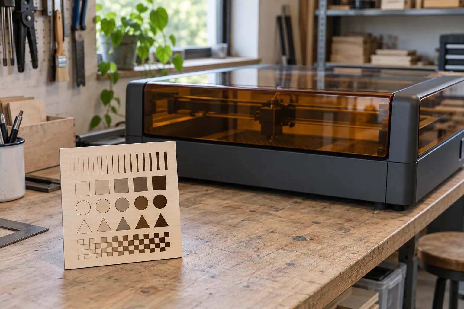
A test file compares settings; it does not define them
A material test normally arranges sample shapes in a grid so you can compare outcomes across selected settings. The grid is only the geometry and organization. The laser source, controller, software, focus, material and finish determine which settings are valid and what the result means.
Do not reuse a speed-and-power chart from another machine as a preset. Even the same nominal material can vary with thickness, coating, color, batch and part geometry. A useful test begins with a known material and a documented, machine-appropriate starting range.
Use the machine software’s material-test tool when available
Some software can generate a parameter grid directly. The LightBurn Material Test guide explains how its generator varies supported settings such as speed, power, interval or passes, depending on the laser. Its first material test walkthrough starts with a spare piece of the material and notes that settings should be reconsidered when the material changes.
Follow the instructions for your own control software. Confirm the units, machine origin, test dimensions and preview before starting. LightBurn warns that confusing millimeters per second with millimeters per minute can change exposure substantially, so check the displayed units rather than copying a number without context.
Keep the test material and setup representative
Use an offcut that matches the intended job in material, thickness, surface finish and batch. Set focus and hold the sample in the same way you plan to use for the project. Keep the enclosure closed and the documented exhaust connected; remain at the machine and follow its fire and emergency procedures.
Start with a small area. For an engraving-only comparison, configure the sample as engraving in your software and do not add cut operations unless you have separately verified the material and machine guidance for cutting. If the material is unknown or the coating is undocumented, do not use a test run as a substitute for identifying it.
Judge the result against the job, not the darkest square
Compare legibility, fine-line detail, edge quality, surface damage and cleanup—not just darkness. A result that looks strongest on a small cell may behave differently on a larger mark because dimensions, heat and motion affect the process. Recheck the candidate setting on a sample close to the real job size before using it for production.
If the task is a QR code or small lettering, check it at the final size and surface finish. The QR-code guide covers module size, contrast and reader verification. Keep cutting tests separate from engraving tests; they have different success criteria and may create more heat or fire risk.
Download the geometry-only test grid
Download the Laser Bench SVG test grid. It contains simple vector sample geometry only—no machine profile, laser mode, speed, power, frequency or pass count is embedded. Inspect the imported size and layer assignments in your software, choose an engraving operation, and set parameters only within the documented range for your exact machine and material.
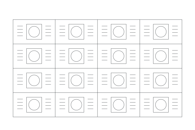
If your software has a native material-test generator, use that instead of treating this SVG as a controller-ready preset. The file is a reusable layout aid, not a certification, material-compatibility check or guarantee of a safe result.
Record enough detail to repeat a good result
Save the test beside the project file with the machine model, source or module, lens or field where relevant, software and controller version, material supplier and batch, dimensions, focus method, exhaust setup, settings and a photo of the sample. Note what the mark must achieve and why one cell was selected.
Re-test when a material, coating, machine configuration or critical setup changes. Treat the saved result as a starting point for that documented job—not a universal setting for every piece with a similar label.
What to hold constant and what to record
| Test detail | Keep consistent | Record for reuse |
|---|---|---|
| Material | Same identified stock, thickness and finish. | Supplier, product, batch and surface coating. |
| Machine setup | Same laser, focus method, fixture and enclosure. | Model, source/module, lens and software version. |
| Test range | Change only supported parameters in a controlled grid. | Units, min/max values, passes and other fixed settings. |
| Evaluation | Judge at the intended mark size and lighting. | Contrast, detail, damage, cleanup and a sample photo. |
Before you compare machines
- Identify and confirm the material before placing it in the machine.
- Use settings within the manufacturer’s documented range.
- Check units, size, origin, preview, enclosure and extraction before running.
- Change one supported parameter at a time and supervise the entire test.
- Record the material batch and full setup; re-test when critical inputs change.
Questions worth answering first
Will one laser engraver test file work on every machine?
The geometry may import into different software, but controller settings, units, laser source and safe parameter ranges vary. Inspect the file and configure it for the exact machine rather than treating it as a universal preset.
Can I use the same test settings on different wood or plywood?
Not automatically. Species, glue, thickness, moisture, finish and batch can change the result. Verify the stock and test an offcut that represents the job.
Should I include cutting in a material test?
Only when you have confirmed the material is suitable and the machine maker documents the cut process. Keep cut tests separate from engraving comparisons and follow the machine’s fire-safety and extraction instructions.
What settings should I put in a test grid?
Use a range supported by the laser manufacturer and vary only parameters the machine and software expose for that source. This page intentionally does not prescribe universal power, speed or frequency values.