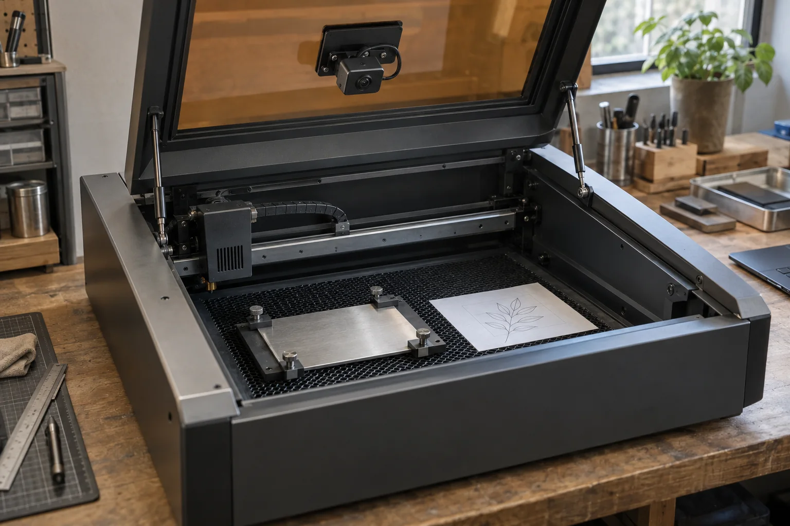
Treat the camera as an alignment aid
A camera preview can help you place a design relative to the material already on the bed. Depending on the machine, the camera may show most of the work area from the lid, a smaller close-up around the laser head, or both. Those views solve different layout problems; a wide overview is not automatically a precision registration system.
Check what the feature actually does in the manufacturer’s current documentation. Does it capture a static image, show a live view, map the bed into the design software, recognize a printed reference, or correct placement after calibration? Product photos often use “camera positioning” broadly, while the supported workflow can be specific to one machine, lens and software version.
Check registration on the actual fixture
The camera has to translate pixels in its image into positions in the machine’s work area. Perspective, lens distortion and the distance between the camera and the part can affect that mapping. A preview that lines up on a flat bed may shift when a fixture raises the work, a curved part sits at an angle, or the material is placed differently.
Use a fixed reference edge or a fixture stop so the part returns to the same position. Keep the camera view, bed height and orientation consistent, and test on the same kind of part that will be marked. On a small item, a slight rotation or a few millimeters of movement can matter more than the screen preview suggests.
Calibration belongs to the machine and software
Some camera workflows include a calibration routine to correct the difference between the image and the machine’s processing position. Follow the steps for the exact model and software; do not copy a calibration pattern or settings from another engraver. As one model-specific example, xTool’s P3 guide describes separate distant-view and close-view camera calibration.
If the machine is moved or the camera, lens, head, bed or supported software changes, check the maker’s instructions to learn whether recalibration is required. Keep a record of the machine configuration and calibration date. Calibration can improve a mapping, but it does not hold a loose part still or make a curved surface behave like a flat one.
Compare the camera with the job, not the product photo
Before buying, compare the camera’s coverage with the parts you expect to process. Ask whether the entire bed is visible, how the preview responds to different workpiece heights, whether the software supports your operating system, and whether the camera can be calibrated by the user. For cups, rings or irregular shapes, ask how the documented workflow handles rotation, focus and fixture references.
A camera may reduce manual measuring for repeat jobs, but it does not replace workholding, material identification or a physical proof. The accessories guide covers fixtures and alignment tools; the golf-club workflow shows why curved, reflective parts need stable references.
Validate placement before a finished part
Use the manufacturer-approved preview or outline function to check the design area, then confirm placement on a representative sample using the machine’s documented procedure. Inspect the mark against a known reference and repeat the setup on another part. A screen overlay alone does not prove that the finished mark is centered, in focus or repeatable.
Record the artwork revision, fixture stop, part orientation and any camera calibration used. If the job has a tight tolerance, a customer approval step or a required inspection method, define that acceptance check before production. This guide is about choosing and planning a feature; it is not an operating procedure for any particular laser.
Camera-assisted alignment checks
| Capability | What to verify | Why it matters |
|---|---|---|
| View coverage | Bed overview, close-up view or both; usable area and blind spots. | The camera must show the part and reference you need to place. |
| Calibration | Supported model, software version and maker’s calibration process. | Image-to-bed mapping is specific to the camera and machine setup. |
| Part height | Fixture, riser, rotary and curved-part workflow. | A changed camera-to-part distance can alter apparent position. |
| Repeatability | Physical stop, fixture reference and a second-part check. | The preview cannot prevent a workpiece from shifting or rotating. |
| Proof | Actual material, intended mark size and agreed inspection. | A screen preview is not evidence that the finished mark meets tolerance. |
Before you compare machines
- Decide whether the job needs an overview, close-up placement or calibrated registration.
- Confirm the camera workflow and calibration instructions for the exact machine and software.
- Check how the preview handles fixtures, raised parts, curvature and the usable work area.
- Use a stable physical reference and validate placement on a representative sample.
- Record the artwork, fixture orientation and inspection method for repeat jobs.
Questions worth answering first
Does a laser engraver camera guarantee exact placement?
No. It can assist with visual placement, but accuracy depends on the camera mapping, calibration, machine setup, workpiece height and fixturing. Verify the mark on a representative part.
Do I still need a fixture if my laser engraver has a camera?
Usually, yes for repeat work. A camera can show where a part appears, but a fixture or physical stop helps keep the part in the same position and orientation.
Will the camera work on a raised or curved object?
Only if the machine maker documents a suitable workflow for that geometry and height. A preview calibrated to a flat bed may not map accurately to a raised or curved surface.
When should I recalibrate the camera?
Use the exact machine maker’s guidance. Some models provide a calibration procedure; whether it is needed after a move, hardware change or software update depends on that system.